 |
|
 04-14-2016, 09:06 PM
|
#1
|
|
Senior Member
Join Date: Jul 2010
Location: Rockwell, North Carolina
Trailer: 2015 Escape 5TA
Posts: 170
|
5.0 TA landing gear control modification
I have never liked where the control switches for the front gear were located. I had to place my hand on the switches and then stand on my head to see the gear to guide them to their landing spot. This week I added a chord and box for the switches and placed a connection point in the LP storage area.
|

|

|
|
04-15-2016, 12:20 AM
|
#2
|
|
Site Team
Join Date: Jun 2014
Location: Canyon Lake, Texas
Trailer: 2015 19 "Past Tents", 2021 F150 Lariat 2.7L EB
Posts: 10,222
|
That is a great idea Barry.
Sent from my iPhone using Tapatalk
__________________
"You can't buy happiness, but you can buy an RV. And that is pretty close."
|
|
|
|
|
04-15-2016, 12:49 AM
|
#3
|
|
Senior Member
Join Date: Dec 2012
Location: Edmonton, Alberta
Trailer: 1979 Boler B1700
Posts: 14,935
|
I think that's a great idea, too. I see the connector is a 7-pin RV-style trailer cable connector - that has lots of circuits and big contacts to handle the current.
One could even put a socket on each side of the trailer, to be able to use the switches at whichever side is more convenient... just in case one is raising the front to level and needs to watch clearance one side at the back.
|
|
|
|
|
04-15-2016, 01:00 AM
|
#4
|
|
Senior Member
Join Date: Sep 2013
Location: Ventura County, California
Trailer: 2013 19 Escape
Posts: 7,204
|
Quote:
Originally Posted by strawbarry

I have never liked where the control switches for the front gear were located. I had to place my hand on the switches and then stand on my head to see the gear to guide them to their landing spot. This week I added a chord and box for the switches and placed a connection point in the LP storage area.
|
Very nice mod ! Pat
|
|
|
|
|
04-15-2016, 07:18 AM
|
#5
|
|
Senior Member
Join Date: Oct 2008
Location: Calgary, Alberta
Trailer: 2017 Escape 5.0 TA
Posts: 15,543
|
Nice, I like that idea. I assume there are 3 wires, correct? I am placing an order soon with Cnlinko, so for less that $10 can order one of these in a 3 pin.

__________________
2017 Escape 5.0 TA
2015 Ford F150 Lariat 3.5L EcoBoost
2009 Escape 19 (previous)
Most folks are about as happy as they make up their minds to be. Abraham Lincoln
|
|
|
|
|
04-15-2016, 07:42 AM
|
#6
|
|
Senior Member
Join Date: Jul 2014
Location: Tampa Bay Area, Florida
Trailer: 2015 Escape 5.0TA (Little Elsie) Extensively Personalized
Posts: 2,969
|
Quote:
Originally Posted by Jim Bennett
Nice, I like that idea. I assume there are 3 wires, correct? I am placing an order soon with Cnlinko, so for less that $10 can order one of these in a 3 pin.
|
Jim, Isn't Cnlinko a Chinese company? Where are you ordering this from? Do they have a distributor in N.A?
__________________
What a long strange trip its been!
|
|
|
|
|
04-15-2016, 07:50 AM
|
#7
|
|
Senior Member
Join Date: Oct 2008
Location: Calgary, Alberta
Trailer: 2017 Escape 5.0 TA
Posts: 15,543
|
Quote:
Originally Posted by C&G in FL
Jim, Isn't Cnlinko a Chinese company? Where are you ordering this from? Do they have a distributor in N.A?
|
Yes, I have been dealing direct with them in China. I must say that the response has been great, and they are very helpful. Each connector is aroun $5 USD. The kicker is that shipping is $25 USD, so I need to order a few to make it worthwhile. The have a lot of good ones to choose from.
They are also available on eBay, though much pricier.
__________________
2017 Escape 5.0 TA
2015 Ford F150 Lariat 3.5L EcoBoost
2009 Escape 19 (previous)
Most folks are about as happy as they make up their minds to be. Abraham Lincoln
|
|
|
|
|
04-15-2016, 12:51 PM
|
#8
|
|
Senior Member
Join Date: Aug 2009
Location: Victoria, Vancouver Island, British Columbia
Trailer: 2015 5.0 TA
Posts: 394
|
I do like the idea also as one needs to contort to see the position of the passengers side landing gear. I have not looked in detail yet, but when I unscrewed the rocker switches, there are 8 heavy gauge wires, 4 per switch, I suspect there are common ones within the 8 wires. Does anyone know the wire gauge?
One thing I just noticed is the battery disconnect switch does not effect the landing gear, it still works with the switch off.
|

|
|
|
04-15-2016, 02:30 PM
|
#9
|
|
Senior Member
Join Date: Dec 2012
Location: Edmonton, Alberta
Trailer: 1979 Boler B1700
Posts: 14,935
|
Quote:
Originally Posted by Jim Bennett
I assume there are 3 wires, correct? I am placing an order soon with Cnlinko, so for less that $10 can order one of these in a 3 pin.
|
I really like those connectors, and the 20-amp capacity may be suitable, but I think you need more contacts...
Quote:
Originally Posted by Chris R
I do like the idea also as one needs to contort to see the position of the passengers side landing gear. I have not looked in detail yet, but when I unscrewed the rocker switches, there are 8 heavy gauge wires, 4 per switch, I suspect there are common ones within the 8 wires. Does anyone know the wire gauge?
|
Each switch controls a jack motor, and because that control is bi-directional it is likely a centre-off DPDT reversing switch. That would make one +12V and one return (or "ground") in common between the two, so I'm guessing that six conductors is the minimum to make everything work.
(If I get around to checking the wiring in detail and this is incorrect, I'll post an update/correction.)
Barry, how many contacts of that connector are you using?
|
|
|
|
|
04-15-2016, 02:51 PM
|
#10
|
|
Senior Member
Join Date: Dec 2012
Location: Edmonton, Alberta
Trailer: 1979 Boler B1700
Posts: 14,935
|
I checked an Atwood jack manual (probably not the right one for these jacks, but the wiring should be similar) and found the attached drawing for the wiring of the switch. The red and yellow wires go to the motor, and swap polarity depending on which way you push the rocker switch (extend or retract). The black is the 12 volt supply, and the ground wire is the return side of the power supply.
There are two of these switches in an Escape 5.0/5.0TA, to run the two jacks. Both black and ground could be in common between the two switches, but each would need the capacity to handle the current of two jack motors. That would leave six wires minimum - +12V supply (black) - common between left and right jacks
- ground - common between left and right jacks
- red motor wire - left jack
- yellow motor wire - left jack
- red motor wire - right jack
- yellow motor wire - right jack
Of course wire colours could be different on the model Escape is using.
According to Atwood's installation/operation/maintenance manual, they use a 30-amp fuse, so individual jack wires should be suitable for that (10 gauge?), and common wires should be suitable for 60 amps (8 gauge?) unless there is a lower-rated fuse on the common supply.
|
|
|
|
|
04-15-2016, 04:08 PM
|
#11
|
|
Senior Member
Join Date: Oct 2008
Location: Calgary, Alberta
Trailer: 2017 Escape 5.0 TA
Posts: 15,543
|
Quote:
Originally Posted by Brian B-P
There are two of these switches in an Escape 5.0/5.0TA, to run the two jacks. Both black and ground could be in common between the two switches, but each would need the capacity to handle the current of two jack motors. That would leave six wires minimum
|
I am interested to hear from Barry just how they were switched in the first place, and what he used in his remote.
In your scenario, could you not eliminate the neutral wire? There is no need to switch it. Plus maybe either two separate positive leads would be better than one heavier gauge, or you could use a SPDT switch between the two control switches so that only one could be used at the same time.
Maybe the latter idea would be too slow operating each leg at a time. Do folks usually put down both at once?
__________________
2017 Escape 5.0 TA
2015 Ford F150 Lariat 3.5L EcoBoost
2009 Escape 19 (previous)
Most folks are about as happy as they make up their minds to be. Abraham Lincoln
|
|
|
|
|
04-15-2016, 04:13 PM
|
#12
|
|
Senior Member
Join Date: Sep 2009
Location: Southwick, Massachusetts
Trailer: None, sold my 2014 5.0TA
Posts: 7,124
|
Quote:
Originally Posted by Jim Bennett
. Do folks usually put down both at once?
|
We do, bring them down till the 1st touches ground, then drop the 2nd till it too touches, then both again till you're happy.
__________________
Happy Motoring
Bob
|
|
|
|
|
04-15-2016, 04:14 PM
|
#13
|
|
Senior Member
Join Date: Oct 2008
Location: Calgary, Alberta
Trailer: 2017 Escape 5.0 TA
Posts: 15,543
|
Quote:
Originally Posted by Chris R
I do like the idea also as one needs to contort to see the position of the passengers side landing gear. I have not looked in detail yet, but when I unscrewed the rocker switches, there are 8 heavy gauge wires, 4 per switch, I suspect there are common ones within the 8 wires. Does anyone know the wire gauge?
One thing I just noticed is the battery disconnect switch does not effect the landing gear, it still works with the switch off.
|
I am curious to know how these are wired up. I would think there are only 3 wires to the switches themselves, one common positive, and the two switched leads to each direction of the jack.
That darn Barry guy anyway. Throws a neat solution out there for us, with no details of what he did. 
__________________
2017 Escape 5.0 TA
2015 Ford F150 Lariat 3.5L EcoBoost
2009 Escape 19 (previous)
Most folks are about as happy as they make up their minds to be. Abraham Lincoln
|
|
|
|
|
04-15-2016, 04:15 PM
|
#14
|
|
Senior Member
Join Date: Aug 2009
Location: Victoria, Vancouver Island, British Columbia
Trailer: 2015 5.0 TA
Posts: 394
|
Let's just say they are not the fastest jacks, I put them both up/down together.
|
|
|
|
|
04-15-2016, 04:43 PM
|
#15
|
|
Senior Member
Join Date: Oct 2008
Location: Calgary, Alberta
Trailer: 2017 Escape 5.0 TA
Posts: 15,543
|
Quote:
Originally Posted by padlin
We do, bring them down till the 1st touches ground, then drop the 2nd till it too touches, then both again till you're happy.
|
Quote:
Originally Posted by Chris R
Let's just say they are not the fastest jacks, I put them both up/down together.
|
I kinda figured this would be the routine. Good to know, thanks.
I imagine to be faster, they would have to have bigger motors, and draw more current too.
__________________
2017 Escape 5.0 TA
2015 Ford F150 Lariat 3.5L EcoBoost
2009 Escape 19 (previous)
Most folks are about as happy as they make up their minds to be. Abraham Lincoln
|
|
|
|
|
04-15-2016, 06:06 PM
|
#16
|
|
Senior Member
Join Date: Dec 2012
Location: Edmonton, Alberta
Trailer: 1979 Boler B1700
Posts: 14,935
|
Reversing motor wiring
Quote:
Originally Posted by Jim Bennett
I am interested to hear from Barry just how they were switched in the first place, and what he used in his remote.
|
Me, too. 
Quote:
Originally Posted by Jim Bennett
In your scenario, could you not eliminate the neutral wire? There is no need to switch it.
|
Quote:
Originally Posted by Jim Bennett
I would think there are only 3 wires to the switches themselves, one common positive, and the two switched leads to each direction of the jack.
|
If by "neutral" you mean return/ground/negative, then no... you still need to complete the circuit. There are only two wires to a motor (yellow and red in the diagram I found) and of them one is positive and the other is negative, but which is which depends on the direction the jack is to move.
You can't connect the return/negative side of each motor directly to ground (avoiding the switches and the remote cable) because there is no consistent return/negative side: it is one wire when extending, and the other wire when retracting, so it actually needs to be switched.
If you look at the switch symbol used in the Atwood wiring diagram, it suggests a classic reversing switch consisting of a DPDT switch plus built-jumpers . Here's an example from a random web site more clearly illustrating this:
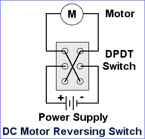
It is the same as the "4-way" switch used in a common home "traveler" system so that three or more switches can control the same light, except that the jack switch has a centre off position.
This works because common DC motors run in a direction determined by the polarity of the power applied:
|
|
|
|
|
04-15-2016, 06:09 PM
|
#17
|
|
Senior Member
Join Date: Dec 2012
Location: Edmonton, Alberta
Trailer: 1979 Boler B1700
Posts: 14,935
|
One power wire or two? Running jacks together?
Quote:
Originally Posted by Jim Bennett
Plus maybe either two separate positive leads would be better than one heavier gauge, or you could use a SPDT switch between the two control switches so that only one could be used at the same time.
|
I agree that it is more straightforward - and allows more connector options - to use separate power and return wires for each motor; that would be eight wires to the switch set.
Moving both together is essential to adjusting pitch without twisting (racking) the trailer. You can extend one at a time to reach the ground, but once they are supporting the trailer if you move only one at a time you would need to keep switching back and forth between them as you adjust height to avoid twist.
|
|
|
|
|
04-15-2016, 06:09 PM
|
#18
|
|
Senior Member
Join Date: Dec 2012
Location: Edmonton, Alberta
Trailer: 1979 Boler B1700
Posts: 14,935
|
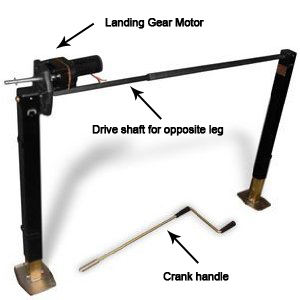
Fifth-wheel landing gear jack types
Common two-leg "landing gear" systems for fifth-wheel trailers avoid this wo-switch complexity by having only one motor driving both legs (via a shaft across the trailer) and being incapable of moving the legs separately. They have pinned leg extensions which are lowered by hand (different amounts if necessary due to uneven ground) before power-extending the legs as a set for leveling or to line up with the hitch. Those systems are typically quite heavy (because they come only in large sizes); I assume that's why Escape uses two jacks each of which would normally be used as a single jack on the tongue of a conventional trailer.
A conventional single-motor landing gear:
|
|
|
|
|
04-15-2016, 06:39 PM
|
#19
|
|
Senior Member
Join Date: Oct 2008
Location: Calgary, Alberta
Trailer: 2017 Escape 5.0 TA
Posts: 15,543
|
Quote:
Originally Posted by Brian B-P
Me, too.
If by "neutral" you mean return/ground/negative, then no... you still need to complete the circuit. There are only two wires to a motor (yellow and red in the diagram I found) and of them one is positive and the other is negative, but which is which depends on the direction the jack is to move.
You can't connect the return/negative side of each motor directly to ground (avoiding the switches and the remote cable) because there is no consistent return/negative side: it is one wire when extending, and the other wire when retracting, so it actually needs to be switched.
If you look at the switch symbol used in the Atwood wiring diagram, it suggests a classic reversing switch consisting of a DPDT switch plus built-jumpers . Here's an example from a random web site more clearly illustrating this:
It is the same as the "4-way" switch used in a common home "traveler" system so that three or more switches can control the same light, except that the jack switch has a centre off position.
This works because common DC motors run in a direction determined by the polarity of the power applied:
|
Yeah, I see what I missed, in needing the "negative" to be switched as well to reverse polarity.
I don't get the 4-way switch reference though, as all they are is a line, or traveller, transfer switch. Do my lights on these circuits come on backwards when the 4-way is switched?
__________________
2017 Escape 5.0 TA
2015 Ford F150 Lariat 3.5L EcoBoost
2009 Escape 19 (previous)
Most folks are about as happy as they make up their minds to be. Abraham Lincoln
|
|
|
|
|
04-15-2016, 06:42 PM
|
#20
|
|
Senior Member
Join Date: Dec 2012
Location: Edmonton, Alberta
Trailer: 1979 Boler B1700
Posts: 14,935
|
Higher-tech: relays
If anyone wants to be able to use much lighter cable and connector, they could use reversing relays mounted in place of the stock switches, and a much lighter-gauge cable to a more compact set of switches carrying only control power for the relays.
These are a couple of examples of a pair of relays set up as a reversing set in one tidy package (one module per jack): I suspect that searching for a 12 volt winch relay or solenoid would find a variety of suitable hardware. These examples have more than twice the capacity required, and to run this type of module only a SPDT momentary-contact switch is needed, which only carries a fraction of one amp and would share a single power source (so with two modules for two jacks that's two switches and five wires: common feed, left motor extend, left motor retract, right motor extend, right motor retract). That's essentially the wiring that I think Jim was expecting, but the trailer's jacks don't have this sort of module built into them.
Jim, you could use the 5-core version of that YP-20 connector from Cnlinko for the these low-power switches - it would have far more current capacity than required. A weatherproof connector like that would not need to be inside a compartment.
In case of relay failure, the stock switches could be retained and the relays wired in parallel with them... as long as you never push any of the original switches at the same time that you are using the relays (that has short-circuit possibilities  )
|
|
|
|
|
|
| Thread Tools |
|
|
| Display Modes |
 Linear Mode Linear Mode
|
 Posting Rules
|
You may not post new threads
You may not post replies
You may not post attachments
You may not edit your posts
HTML code is Off
|
|
|
|
 » Recent Discussions
 |
|
|
|
|
|
|
|
|
|
|
|
|
|
|
|
|
|
|
|
|
|
|
|
|
|
|
|
|
|
|

|


