 |
|
 01-13-2021, 09:42 AM
|
#1
|
|
Senior Member
Join Date: Aug 2015
Location: Naples, New York
Trailer: 2020 Esacpe 19'(Hillbilly Heaven) ETI best named trailer of the year
Posts: 1,204
|
After build Inverter install questions
I am considering adding inverter to my 19' . I would like to be able to run a toaster in the morning. a 60amp draw . I have the factory installed 6 volts in front storage box with 380 watts of solar on roof.Currently The battery wiring is 8 AWG running through a 50 amp thermal fuse. It also appears negative go to the frame and Dc panel ground to the Frame. I assuming the current wiring would not be able to take a 750 watt inverter. So my thinking if i have to rewire the system I might as well go with a 1500 inverter.It should ad value to the trailer. I have done a lot of forum searches and reading on the Subject. I understand if i want to do all outlets i need a transfer switch and install a AC Sub panel. I am also going to install a victron 712 battery monitor. at this point i trying to totally understand the wiring so I can price this out and compare cost to relocating Lithium setup in driver side dinette(thats another subject) I have questions on the factory install .
What size AWG does ETI use and what size fuse? is that fuse at the battery terminal? I assume the do not use the frame ground?
I guess what i am wondering if i install 4 AWG ( or is 2AWG required)from the battery to the inverter and put a 200 amp fuse at the battery terminal can I leave the current DC battery wiring like it is? The positive inverter feed would no go trough battery switch.
The other question is the monitor shut wiring.The frame ground and battery location complicate the install. Ideal the shunt would be at the battery terminal. If i locate it just inside the shell it be weather protected and all wiring would be so mush easier. I have a email out to victron asking what the affects of the shunt being 3-4 foot away from battery. currently the Dc panel ground to the frame and the battery grounds to the frame . How would i wire this so all loads and inverter run Trough the shunt?
 You guys told me if i ever thought I need the inverter to get the factory install..
|

|

|
|
01-13-2021, 09:51 AM
|
#2
|
|
Senior Member
Join Date: Oct 2017
Location: Kelowna, British Columbia
Trailer: 2018 Escape 19
Posts: 2,718
|
Here is my short answer for toast in the morning. 
|
|
|
|
|
01-13-2021, 02:45 PM
|
#3
|
|
Senior Member
Join Date: Mar 2016
Location: Burlington Twp., New Jersey
Trailer: 2010 Escape 19
Posts: 7,146
|
Quote:
Originally Posted by NEWYORKHILLBILLY

I guess what i am wondering if i install 4 AWG ( or is 2AWG required)from the battery to the inverter and put a 200 amp fuse at the battery terminal can I leave the current DC battery wiring like it is? The positive inverter feed would no go trough battery switch.
The other question is the monitor shunt wiring.The frame ground and battery location complicate the install. Ideal the shunt would be at the battery terminal. If i locate it just inside the shell it be weather protected and all wiring would be so mush easier. I have a email out to victron asking what the affects of the shunt being 3-4 foot away from battery. currently the Dc panel ground to the frame and the battery grounds to the frame . How would i wire this so all loads and inverter run Trough the shunt?
|
See attached wiring schematic from tdf-texas as a basis for conversation. Your inverter circuit if wired to the battery directly is independent from the existing DC trailer wiring except you need to remember to upgrade the link between your two 6V batteries. If I can make a recommendation I would move the batteries inside now if you think you are going lithium. Mine are inside the passenger dinette seat due to being displaced from the tongue for mini-split condenser. I recently upgraded the main DC wiring to 6AWG with new 60A Maxi-fuse and disconnect switch but that is unrelated to your main question. For the Victron I believe you want the shunt as close to the battery as possible and the inverter (and all other loads) would land on the load side of the shunt. Having the batteries and all wiring inside is much easier as I contemplate Victron BMV-712 battery monitor, lithium batteries and an inverter similar to you. Following with interest and assisting where I can.
|
|
|
|
|
01-13-2021, 03:06 PM
|
#4
|
|
Senior Member
Join Date: Oct 2013
Location: Phoenix, Arizona
Trailer: 2015 Escape 19 "Seventy Degrees"
Posts: 3,495
|
Absolutely second Dave's suggestion of moving the batteries in under dinette. You should do AGM or Lithium if you're going to move them in.
I'm putting the new Battleborn's under the DS dinette bench and the inverter under the PS front bench.
It is so much easier to deal with the wiring and components on the 19 if the batteries are located under the dinette with everything else.
I'm also not using a sub-panel as it's not really necessary. The Gopower 30amp Xfer switch has a 15a auxillary hookup on the shore power side that you simply wire your WFCO converter module to and you can use the existing AC side of the WFCO as is by just flipping the current AC in wire over to the Xfer switch, and running a new AC wire from EMS to Xfer switch.
|
|
|
|
|
01-13-2021, 04:33 PM
|
#5
|
|
Senior Member
Join Date: Dec 2012
Location: Edmonton, Alberta
Trailer: 1979 Boler B1700
Posts: 14,935
|
Quote:
Originally Posted by Greg A
I'm also not using a sub-panel as it's not really necessary. The Gopower 30amp Xfer switch has a 15a auxillary hookup on the shore power side that you simply wire your WFCO converter module to and you can use the existing AC side of the WFCO as is by just flipping the current AC in wire over to the Xfer switch, and running a new AC wire from EMS to Xfer switch.
|
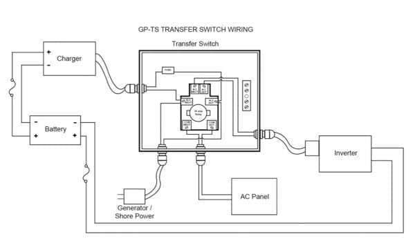
If I understand this configuration correctly, it places the transfer switch before the WFCO AC panel, instead of between one branch circuit of the WFCO panel and an auxiliary panel. That works, however: - it undesirably allows the operation of inappropriate loads (such as the 120 V AC element of the refrigerator, optional 120 V AC element of the water heater, and air conditioner) on the inverter; and,
- the main breaker is downstream of the transfer switch (which works, but is not likely correct).
These are both manageable concerns (especially for a trailer without the 2-way water heater or air conditioner), but I think that anyone building a system this way should be aware of them.
If this is the Go Power GP-TS-30, according to the manual the auxiliary hookup on the shore power side is simply connected in parallel with the shore power input - it's a wiring convenience, but it has no overcurrent protection and functions no differently from just connecting the converter/charger to the shore power in a junction box before the transfer switch.
|
|
|
|
|
01-13-2021, 06:15 PM
|
#6
|
|
Senior Member
Join Date: Feb 2013
Location: Santa Rosa County, Florida
Trailer: 2014 Escape 21 Tow: 2024 Toyota Tundra
Posts: 3,105
|
Speaking of inverters: My 2014 Escape 21 was equipped with an inverter, which at the time was the Samlex 1500W model. It was not mounted directly to the trailer floor, but instead was mounted to a small square of plywood which was screwed to the floor. Any idea why Escape did this?
__________________
Mike Lewis
She don't lie, she don't lie, she don't lie-- propane
Photos and travelogues here: mikelewisimages.com
|
|
|
|
|
01-13-2021, 08:26 PM
|
#7
|
|
Senior Member
Join Date: Aug 2015
Location: Naples, New York
Trailer: 2020 Esacpe 19'(Hillbilly Heaven) ETI best named trailer of the year
Posts: 1,204
|
Quote:
Originally Posted by rubicon327
See attached wiring schematic from tdf-texas as a basis for conversation. Your inverter circuit if wired to the battery directly is independent from the existing DC trailer wiring except you need to remember to upgrade the link between your two 6V batteries. If I can make a recommendation I would move the batteries inside now if you think you are going lithium. Mine are inside the passenger dinette seat due to being displaced from the tongue for mini-split condenser. I recently upgraded the main DC wiring to 6AWG with new 60A Maxi-fuse and disconnect switch but that is unrelated to your main question. For the Victron I believe you want the shunt as close to the battery as possible and the inverter (and all other loads) would land on the load side of the shunt. Having the batteries and all wiring inside is much easier as I contemplate Victron BMV-712 battery monitor, lithium batteries and an inverter similar to you. Following with interest and assisting where I can.
|
The diagram is helpful . I see the converter wire is 2/0 does escape us That large of wire? I was thinking 2AWG.
|
|
|
|
|
01-13-2021, 08:51 PM
|
#8
|
|
Senior Member
Join Date: Nov 2015
Location: Baytown, Texas
Trailer: 2017 21' Escape - upgraded version
Posts: 2,697
|
Quote:
Originally Posted by NEWYORKHILLBILLY
The diagram is helpful . I see the converter wire is 2/0 does escape us That large of wire? I was thinking 2AWG.
|
Here's the completed wiring diagram if it helps. Keep in mine - this is for my trailer that has all the wiring corrections made.
My trailer originally came with 2AWG inverter cables - they were upgraded to the 2/0 due to the voltage drop when trying to use the inverter.
__________________
Normal people believe that if it ain't broke, don't fix it.
Engineers believe in fixing it so that it never breaks.
|
|
|
|
|
01-13-2021, 09:04 PM
|
#9
|
|
Senior Member
Join Date: Mar 2016
Location: Burlington Twp., New Jersey
Trailer: 2010 Escape 19
Posts: 7,146
|
Quote:
Originally Posted by NEWYORKHILLBILLY
The diagram is helpful . I see the converter wire is 2/0 does escape us That large of wire? I was thinking 2AWG.
|
I think Escape is around 2AWG on their 1500W inverter but not 100% positive. I’m sure someone knows. But look at the specifics of your installation and overall distance to battery (positive + negative lead lengths combined). You don’t want to have a large voltage drop in the wiring shutting your inverter down prematurely. Bigger is better. You’ll find these older posts from Jon V. very informative. If I do a 1500W inverter I will most likely be using 0 AWG and maybe 2/0 if it’s a further run than I predict or I’m otherwise convinced by tdf-Texas or one of the other electrical wizards.
https://www.escapeforum.org/forums/f...html#post23285
https://www.escapeforum.org/forums/f...html#post91651
|
|
|
|
|
01-13-2021, 10:55 PM
|
#10
|
|
Senior Member
Join Date: Apr 2014
Location: Arvada, Colorado
Trailer: 2015 E'21 - 'Velocity'. Tow: Toyota Tacoma V6, 4X4, manual.
Posts: 1,692
|
Quote:
Originally Posted by rubicon327
I think Escape is around 2AWG on their 1500W inverter but not 100% positive. Im sure someone knows. But look at the specifics of your installation and overall distance to battery (positive + negative lead lengths combined). You dont want to have a large voltage drop in the wiring shutting your inverter down prematurely. Bigger is better. Youll find these older posts from Jon V. very informative. If I do a 1500W inverter I will most likely be using 0 AWG and maybe 2/0 if its a further run than I predict or Im otherwise convinced by tdf-Texas or one of the other electrical wizards.
|
A rough rule-of-thumb example: If your combined length is 12 feet, and the proper wire gauge is 2/0 for your inverter load, then shortening the round trip by half - to 6 feet - will let you reduce the wire size to 0. Note: This could cut your wire cost down by 75%; shorter and thinner wire = happier credit card.
--
Alan
|
|
|
|
|
01-13-2021, 11:35 PM
|
#11
|
|
Senior Member
Join Date: Feb 2020
Location: East of Austin, Texas
Trailer: 2021 Escape 5.0 / 2022 F150 SuperCab
Posts: 2,908
|
Quote:
Originally Posted by alanmalk
A rough rule-of-thumb example: ......
|
Please take care - that "rough rule of thumb" does not account for conductor cross section/amp criteria (sometimes referenced as the 'circular mils/amp criteria') which is independent of the length of the conductor.
|
|
|
|
|
01-14-2021, 10:48 AM
|
#12
|
|
Senior Member
Join Date: Oct 2013
Location: Phoenix, Arizona
Trailer: 2015 Escape 19 "Seventy Degrees"
Posts: 3,495
|
Quote:
Originally Posted by Brian B-P
If I understand this configuration correctly, it places the transfer switch before the WFCO AC panel, instead of between one branch circuit of the WFCO panel and an auxiliary panel. That works, however: - it undesirably allows the operation of inappropriate loads (such as the 120 V AC element of the refrigerator, optional 120 V AC element of the water heater, and air conditioner) on the inverter; and,
- the main breaker is downstream of the transfer switch (which works, but is not likely correct).
These are both manageable concerns (especially for a trailer without the 2-way water heater or air conditioner), but I think that anyone building a system this way should be aware of them.
If this is the Go Power GP-TS-30, according to the manual the auxiliary hookup on the shore power side is simply connected in parallel with the shore power input - it's a wiring convenience, but it has no overcurrent protection and functions no differently from just connecting the converter/charger to the shore power in a junction box before the transfer switch.
|
Discussed this with Jon, and his concerns as well, but when walked through didn’t seem to be a problem. Videos on this approach seem solid as well.
I don’t have dual water heater, only run fridge on propane(even when on shore power), and only use AC on shore power or gen. I could probably run the AC with the Lithium’s/Invertrer for a short bit, but no need to do that. May have to test it, my friends setup can run AC about 3 hrs, but he has much larger capacity.
The auxiliary in the Xfer switch is fused with 15a fuse so it is protected. Converter will only be powered when on shore power/gen which is correct install to prevent loop.
Inverter will have an off/on remote and won’t be online for long stretches, just when needed.
Good points for sure, and after walking through them, I’m not finding a real downside for my setup/situation.
|
|
|
|
|
01-14-2021, 11:03 AM
|
#13
|
|
Senior Member
Join Date: Aug 2015
Location: Naples, New York
Trailer: 2020 Esacpe 19'(Hillbilly Heaven) ETI best named trailer of the year
Posts: 1,204
|
Quote:
Originally Posted by Greg A
Discussed this with Jon, and his concerns as well, but when walked through didnt seem to be a problem. Videos on this approach seem solid as well.
I dont have dual water heater, only run fridge on propane(even when on shore power), and only use AC on shore power or gen. I could probably run the AC with the Lithiums/Invertrer for a short bit, but no need to do that. May have to test it, my friends setup can run AC about 3 hrs, but he has much larger capacity.
The auxiliary in the Xfer switch is fused with 15a fuse so it is protected. Converter will only be powered when on shore power/gen which is correct install to prevent loop.
Inverter will have an off/on remote and wont be online for long stretches, just when needed.
Good points for sure, and after walking through them, Im not finding a real downside for my setup/situation.
|
Do you have a link to the video on this? I like to understand it better.
|
|
|
|
|
01-14-2021, 02:35 PM
|
#14
|
|
Senior Member
Join Date: Dec 2012
Location: Edmonton, Alberta
Trailer: 1979 Boler B1700
Posts: 14,935
|
Quote:
Originally Posted by Greg A
I don’t have dual water heater, only run fridge on propane(even when on shore power), and only use AC on shore power or gen. I could probably run the AC with the Lithium’s/Invertrer for a short bit, but no need to do that.
|
That's a good scenario; everyone has to assess their own situation. 
Quote:
Originally Posted by Greg A
The auxiliary in the Xfer switch is fused with 15a fuse so it is protected.
|
Good point - while the transfer switch is upstream of the overcurrent protection, all loads are on protected (by fuse or main breaker) circuits.  There's no breaker for the converter, but I had missed the fuse in this diagram.
Anyone using this configuration may want to add a switch in the circuit to the converter, since (without a breaker) there is no way to turn off the converter when plugged into shore power, for troubleshooting or any other reason.
|
|
|
|
|
01-14-2021, 03:09 PM
|
#15
|
|
Senior Member
Join Date: Oct 2013
Location: Phoenix, Arizona
Trailer: 2015 Escape 19 "Seventy Degrees"
Posts: 3,495
|
Quote:
Originally Posted by NEWYORKHILLBILLY
Do you have a link to the video on this? I like to understand it better.
|
There are quite a few, but this was the first one I found that explained this relatively new transfer switch from Go Power offering the auxiliary 15a Converter/charger line.
https://youtu.be/iASOOzUCRto
https://www.rvwithtito.com/articles/...automatically/
I haven't watched this one all the way through yet, but he seems to be doing the exact same approach for a Van system.
The diagram Brian posted above from the Go Power manual diagram is pretty straightforward on the wiring of the Transfer switch with the auxiliary line going to the Converter/charger. Our converter/charger is a module in the WFCO panel and you simply have to remove the converter/charger module wiring from the 15a breaker and wire it to the auxiliary line you run into the WFCO from the transfer switch. This will only power the converter/charger when on shore power which is what you want. (Bonus: you'll have a free 15a breaker to wire up an option in the future)
This method really simplifies installing an inverter to power all your outlets when off grid and they're needed.
Again, it won't hurt anything, just drain batteries quicker but you need to make sure you're not running electric side of Water Heater(if you have that), Fridge on AC or the AC. Of course, if you're boondocking off grid when you need the inverter, all of those things shouldn't be running anyway. 
At first, I was questioning this approach because it was so much simpler, but the more I've designed the system I can't see the downside for my situation. Saves $$$ and time and seems to be a solid approach that makes sense the more I look at it. As I mentioned earlier, everything becomes even simpler when you move the batteries inside under the dinette where all the electrical lives on the 19.
I'll have pictures up over the next month as I move forward with the wiring.
|
|
|
|
|
01-14-2021, 03:12 PM
|
#16
|
|
Senior Member
Join Date: Oct 2013
Location: Phoenix, Arizona
Trailer: 2015 Escape 19 "Seventy Degrees"
Posts: 3,495
|
Quote:
Originally Posted by Brian B-P
Anyone using this configuration may want to add a switch in the circuit to the converter, since (without a breaker) there is no way to turn off the converter when plugged into shore power, for troubleshooting or any other reason.
|
Good idea on the switch. I'll most likely incorporate that into the plan.
|
|
|
|
|
01-14-2021, 09:39 PM
|
#17
|
|
Senior Member
Join Date: Aug 2015
Location: Naples, New York
Trailer: 2020 Esacpe 19'(Hillbilly Heaven) ETI best named trailer of the year
Posts: 1,204
|
Quote:
Originally Posted by Greg A
The diagram Brian posted above from the Go Power manual diagram is pretty straightforward on the wiring of the Transfer switch with the auxiliary line going to the Converter/charger. Our converter/charger is a module in the WFCO panel and you simply have to remove the converter/charger module wiring from the 15a breaker and wire it to the auxiliary line you run into the WFCO from the transfer switch. This will only power the converter/charger when on shore power which is what you want. (Bonus: you'll have a free 15a breaker to wire up an option in the future)
This method really simplifies installing an inverter to power all your outlets when off grid and they're needed.
Again, it won't hurt anything, just drain batteries quicker but you need to make sure you're not running electric side of Water Heater(if you have that), Fridge on AC or the AC. Of course, if you're boondocking off grid when you need the inverter, all of those things shouldn't be running anyway.
At first, I was questioning this approach because it was so much simpler, but the more I've designed the system I can't see the downside for my situation. Saves $$$ and time and seems to be a solid approach that makes sense the more I look at it. As I mentioned earlier, everything becomes even simpler when you move the batteries inside under the dinette where all the electrical lives on the 19.
I'll have pictures up over the next month as I move forward with the wiring. |
I don't have 120v water heater so thats not a problem.I know moving batteries inside would simplify the wiring ,But i not comfortable with lead acids inside(Even in vented box) If i decide to go lithium then I would defiantly move them inside.That would also free up my front storage box for the Honda generator. I am also consider no transfer switch and adding dedicated inverter only AC circuit with 2 plugs on it.
I still have not figured out a good way to do the shunt wiring.
option 1. Mount it inside Just as the neg battery wire enters the shell. Maybe up sizing that length of cable to minimize voltage drop .I would still have to get the temp sensor wire out into the storage box
option2. mount it in A weather proof box outside in the front storage box.I would still need to get the phone wire inside and its not weather proof so it would need some protection .
Also need a solution's to dealing frame ground to insure all the loads travel through the shunt
Eggscape suggestion of the $10 stove top toaster is starting to look better
|
|
|
|
|
01-14-2021, 09:57 PM
|
#18
|
|
Senior Member
Join Date: Nov 2015
Location: Baytown, Texas
Trailer: 2017 21' Escape - upgraded version
Posts: 2,697
|
Quote:
Originally Posted by NEWYORKHILLBILLY
Also need a solution's to dealing frame ground to insure all the loads travel through the shunt
|
The last trailer I rewired that had the batteries in the front and that was using the frame ground as a circuit return path, I removed the frame ground from the battery.
Next, I ran a 2/0 inverter negative cable from the batteries to the Victron shunt mounted inside the trailer. From the Victron shunt load side, I then ran both a 2/0 cable from the shunt to the inverter and a 6 AWG to the WFCO ground stud. The only wire that should be connected to the battery negative is the 2/0 going to the shunt.
The WFCO ground stud already has a frame ground wire attached - that and the frame ground in the 7-pin connection are the only frame grounds needed.
Of course, 200 amp fused 2/0 cable from positive battery terminal to inverter and 60 amp fused 6 AWG wire to the battery cutoff switch.
__________________
Normal people believe that if it ain't broke, don't fix it.
Engineers believe in fixing it so that it never breaks.
|
|
|
|
|
01-14-2021, 09:58 PM
|
#19
|
|
Senior Member
Join Date: Mar 2016
Location: Burlington Twp., New Jersey
Trailer: 2010 Escape 19
Posts: 7,146
|
Quote:
Originally Posted by Greg A
Discussed this with Jon, and his concerns as well, but when walked through didnt seem to be a problem. Videos on this approach seem solid as well.
I dont have dual water heater, only run fridge on propane(even when on shore power), and only use AC on shore power or gen. I could probably run the AC with the Lithiums/Invertrer for a short bit, but no need to do that. May have to test it, my friends setup can run AC about 3 hrs, but he has much larger capacity.
The auxiliary in the Xfer switch is fused with 15a fuse so it is protected. Converter will only be powered when on shore power/gen which is correct install to prevent loop.
Inverter will have an off/on remote and wont be online for long stretches, just when needed.
Good points for sure, and after walking through them, Im not finding a real downside for my setup/situation.
|
I like this approach. No sub panel, no 2nd 30A breaker in the WFCO (which I actually dont think is compliant), charger on auxiliary power and I can choose what is given power from the inverter with flipping of breakers. This is important to me because I eventually intend to try to run our mini-split heat pump on a 1500W inverter paired with lithium batteries.
|
|
|
|
|
01-14-2021, 11:17 PM
|
#20
|
|
Senior Member
Join Date: Aug 2015
Location: Naples, New York
Trailer: 2020 Esacpe 19'(Hillbilly Heaven) ETI best named trailer of the year
Posts: 1,204
|
Quote:
Originally Posted by tdf-texas
The last trailer I rewired that had the batteries in the front and that was using the frame ground as a circuit return path, I removed the frame ground from the battery.
Next, I ran a 2/0 inverter negative cable from the batteries to the Victron shunt mounted inside the trailer. From the Victron shunt load side, I then ran both a 2/0 cable from the shunt to the inverter and a 6 AWG to the WFCO ground stud. The only wire that should be connected to the battery negative is the 2/0 going to the shunt.
The WFCO ground stud already has a frame ground wire attached - that and the frame ground in the 7-pin connection are the only frame grounds needed.
Of course, 200 amp fused 2/0 cable from positive battery terminal to inverter and 60 amp fused 6 AWG wire to the battery cutoff switch.
|
This is very helpful . so if I end up deciding on no inverter and still want the victron 712 monitor. I would remove the frame ground from battery,then run new 6 AWG to shunt ,and then from the shunt load terminal to the converter ground lug. is this correct?
Quote:
Originally Posted by rubicon327
I like this approach. No sub panel, no 2nd 30A breaker in the WFCO (which I actually dont think is compliant), charger on auxiliary power and I can choose what is given power from the inverter with flipping of breakers. This is important to me because I eventually intend to try to run our mini-split heat pump on a 1500W inverter paired with lithium batteries.
|
If you want to run that many split spend some time over on the DIY solar forum . I know you like to tinker and there is guys over there building 280 AH battery for about 600 each with Chinese cells and bms. a pair of those DIY Batteries would give you 560 ah and still weigh less than 2 6 volts . Will prowse the guy that runs that forum has lots of videos on you tube. I spent alot of time over there learning about how to do it.For guys like you and TDF-TEXAS you will understand it much better. Of course there some risk building your own its not like a battle born with a 10 year warranty If i end up going lithium it will be with DIY pack. at this point I not sure if lithium is the right choice for me. when i ordered my trailer i was sure I want lithium. I ordered the 6 volts with the trailer because we had planed a long pickup trip.I new i would need the extra power for Trip. I planed to change them out latter(and still might) . I realized in my trip we had plenty of power and the go power controller never fell below 65% and that was after several cloudy days and temps below freezing at night. My big battery draw is at night when it is below freezing and furnace runs more. It does not help with the batteries outside in the cold temps. DIY Solar Power Forum
|
|
|
|
|
|
 Posting Rules
|
You may not post new threads
You may not post replies
You may not post attachments
You may not edit your posts
HTML code is Off
|
|
|
|
 » Recent Discussions
 |
|
|
|
|
|
|
|
|
|
|
|
|
|
|
|
|
|
|
|
|
|
|
|
|
|
|
|
|
|
|

|


 Linear Mode

