 |
|
 02-20-2022, 07:20 PM
|
#1
|
|
Senior Member
Join Date: Jan 2021
Location: USA, Nunavut
Trailer: Escape
Posts: 274
|
New 5.0 chassis ground problem
Got the new 5.0 a week ago. Began work on our Li batteries install and electrics upgrade. While evaluating the chassis grounds, seeing a problem that perhaps requires some work. There are two chassis grounds under the rear bench.
In the PS rear bench there is an 8awg wire that connects to the main battery negative terminal and runs to a chassis ground under the sewer hose storage tube. That cable is covered with foam & is tucked away safely.
In the middle of the rear bench is another 8awg wire that connects to a busbar with 8 connections on top of the WFCO. It also runs under the trailer and connects to the rear bumper frame. Also, the connector is already damaged. A rock or stick hit will likely take it out.
To address this chassis ground matter think we are going to replace the middle 8awg wire with a 4/0 or 2/0 cable. Also going to cut a channel in the foam to secure it to the chassis is a better spot than the bumper, then refoam over the new cable to protect it. Planning to use this new thicker cable as the main chassis ground on the Lynx Distributer. The batteries will be connected to the Lynx.
Then planning to use a second negative connection on the Lynx as an "equipment ground" going to the busbar at the WHCO, the solar controllers, & the inverter. We think that equipment ground can be a 8awg wire as it shouldn't carry any current unless there is a problem, if we actually understand that WFCO busbar and equipment ground correctly (big if).
Knowing there are electrical experts here, and we are rookies, does this sound like a decent plan?
Thanks in advance for any input.
|

|

|
|
02-20-2022, 08:27 PM
|
#2
|
|
Senior Member
Join Date: Nov 2015
Location: Baytown, Texas
Trailer: 2017 21' Escape - upgraded version
Posts: 2,697
|
Quote:
Originally Posted by Jack!

Got the new 5.0 a week ago. Began work on our Li batteries install and electrics upgrade. While evaluating the chassis grounds, seeing a problem that perhaps requires some work. There are two chassis grounds under the rear bench.
In the PS rear bench there is an 8awg wire that connects to the main battery negative terminal and runs to a chassis ground under the sewer hose storage tube. That cable is covered with foam & is tucked away safely.
In the middle of the rear bench is another 8awg wire that connects to a busbar with 8 connections on top of the WFCO. It also runs under the trailer and connects to the rear bumper frame. Also, the connector is already damaged. A rock or stick hit will likely take it out.
To address this chassis ground matter think we are going to replace the middle 8awg wire with a 4/0 or 2/0 cable. Also going to cut a channel in the foam to secure it to the chassis is a better spot than the bumper, then refoam over the new cable to protect it. Planning to use this new thicker cable as the main chassis ground on the Lynx Distributer. The batteries will be connected to the Lynx.
Then planning to use a second negative connection on the Lynx as an "equipment ground" going to the busbar at the WHCO, the solar controllers, & the inverter. We think that equipment ground can be a 8awg wire as it shouldn't carry any current unless there is a problem, if we actually understand that WFCO busbar and equipment ground correctly (big if).
Knowing there are electrical experts here, and we are rookies, does this sound like a decent plan?
Thanks in advance for any input.
|
There is only one DC ground that should be connected to the trailer battery negative and that is the one that is connected to the WFCO ground lug. As the emergency brake circuit is the only load on this ground, an 8 ga ground wire is sufficient.
There is one DC ground that is connected to the 7 pin JB that grounds the tow vehicle (TV) negative to the trailer frame. This gives the trailer brakes and lights that are powered by the TV a negative return path.
There are safety grounds connected to the trailer frame for 120v devices such as an inverter, WFCO breaker panel, etc. These grounds are required by NEC code.
Below is a wiring diagram for my trailer. All the frame grounds are shown. No other frame grounds are needed.
I realize that you plan to install a completely different electrical system using Lynx - but the same electrical requirements apply. Maybe it would be a good idea to draw up your proposed electrical system such as I did for my trailer and post it on the forum. Tht would allow the EE forum members to critic your system to help you get it right.
__________________
Normal people believe that if it ain't broke, don't fix it.
Engineers believe in fixing it so that it never breaks.
|
|
|
|
|
02-20-2022, 10:17 PM
|
#3
|
|
Senior Member
Join Date: Jan 2021
Location: USA, Nunavut
Trailer: Escape
Posts: 274
|
Quote:
Originally Posted by tdf-texas
There is only one DC ground that should be connected to the trailer battery negative and that is the one that is connected to the WFCO ground lug. As the emergency brake circuit is the only load on this ground, an 8 ga ground wire is sufficient.
There is one DC ground that is connected to the 7 pin JB that grounds the tow vehicle (TV) negative to the trailer frame. This gives the trailer brakes and lights that are powered by the TV a negative return path.
There are safety grounds connected to the trailer frame for 120v devices such as an inverter, WFCO breaker panel, etc. These grounds are required by NEC code.
Below is a wiring diagram for my trailer. All the frame grounds are shown. No other frame grounds are needed.
I realize that you plan to install a completely different electrical system using Lynx - but the same electrical requirements apply. Maybe it would be a good idea to draw up your proposed electrical system such as I did for my trailer and post it on the forum. Tht would allow the EE forum members to critic your system to help you get it right.
|
Thanks for your speedy response and your diagram. Very helpful. I can make a stab at drawing up something like yours but I don't have a drawing tool and will have to do it by hand.
Looking yours over, I can say ETI is doing it differently on the Jan 2022 5.0 trailers. Seems they are making more use of chassis grounds. The neg battery terminal goes straight thru the floor to a chassis ground. Also, just noticed the inverter's equipment ground goes straight thru the floor to the chassis, as well. Took a picture showing both on the PS rear bench.
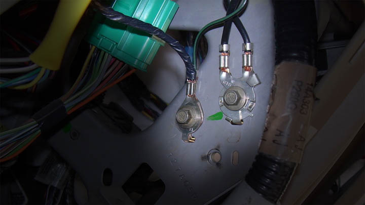
Also, the WFCO negatives are on a busbar placed on top of the power center. There's no "stud". That busbar has another chassis ground that goes straight thru the floor to the rear bumper frame as a chassis ground.
That's the ground that's seen in my previous picture that's half broken on my 5.0 trailer and needs to be redone, perhaps in a better location. Easier to do if the 8awg is adequate, as you mention.
I took a picture of the WFCO negatives busbar and that chassis ground going thru the floor in the middle near the WFCO.
This was why we are considering putting one good chassis ground on the Lynx and then running the WFCO busbar grounds and all the other equipment grounds to the Lynx, as well. The battery would take one spot on the Lynx, the equipment ground a second spot, and the chassis ground a third spot.
|
|
|
|
|
02-21-2022, 08:27 AM
|
#4
|
|
Senior Member
Join Date: Nov 2015
Location: Baytown, Texas
Trailer: 2017 21' Escape - upgraded version
Posts: 2,697
|
Escape using the frame as the negative battery return is not new - just a really bad idea to do it that way. The connection to the frame corrodes over time and forms a high resistance current path for the battery.
I've rewired several Escapes that used that sorry excuse for wiring by running a 2/0 cable from the battery negative to the inverter with a 200 amp fuse at the battery terminal and eliminating the frame ground wire from the battery negative. Why does Escape do this if it is a potential failure point? Because it's cheaper - wire cost money and the less large gauge wire they use adds to the bottom line. 
The stud on the back of the WFCO is where before Escape stacked all the negative return wires along with the wire connected to the frame. That they are using a buss instead is an improvement. 
I would fix the bad crimp on the 8 ga wire and forget about connecting the Lynx to the frame with the exception of the safety ground as required by the Lynx installation manual.
Here is another thread that talks more about the grounding.
https://www.escapeforum.org/forums/f...tml#post401142
__________________
Normal people believe that if it ain't broke, don't fix it.
Engineers believe in fixing it so that it never breaks.
|
|
|
|
|
02-21-2022, 10:44 AM
|
#5
|
|
Senior Member
Join Date: Dec 2012
Location: Edmonton, Alberta
Trailer: 1979 Boler B1700
Posts: 14,935
|
Quote:
Originally Posted by tdf-texas
Escape using the frame as the negative battery return is not new - just a really bad idea to do it that way. The connection to the frame corrodes over time and forms a high resistance current path for the battery.
|
I agree, but I'll also note that if the frame connections were made properly, as they are in automobiles, there would be no problem with using the frame. An alternative to re-wiring would be to make proper connections.
|
|
|
|
|
02-21-2022, 11:56 AM
|
#6
|
|
Senior Member
Join Date: Jan 2014
Location: Lancaster, Virginia
Trailer: 2022 Escape 21C
Posts: 118
|
What is the correct method for creating a proper frame ground? A soon to be new owner is curious to know for future reference.
Ed
|
|
|
|
|
02-21-2022, 01:14 PM
|
#7
|
|
Senior Member
Join Date: Jan 2021
Location: USA, Nunavut
Trailer: Escape
Posts: 274
|
Quote:
Originally Posted by tdf-texas
I've rewired several Escapes that used that sorry excuse for wiring by running a 2/0 cable from the battery negative to the inverter with a 200 amp fuse at the battery terminal and eliminating the frame ground wire from the battery negative.
|
Thanks for the expert guidance from everyone here. Also thanks for the link to the added thread. Great info as usual...
Will definitely eliminate the inverter frame ground, as the inverter will connect to the Lynx along with the batteries.
Plan to use an single safety ground (if that's the correct term) to the frame, rather than the 3 separate frame grounds ETI setup. Plan to continue use of the 8awg frame ground ETI setup for the battery negative terminal. That frame ground is completely protected by the foam and is connected to the frame underneath the sewer storage tube.
Then I can use a single run from that frame ground as the safety ground to the Inverter safety, Lynx safety, Solar controller safety, and end this run at the new WFCO busbar. ETI had a frame ground to the WFCO busbar.
Don't think there needs to be 3 seperate frame grounds if I have that correct..
Also, I'd like to make a run from the WFCO busbar to the negative Lynx. I will have the WFCO positive on the Lynx, in any case, so my less informed mind likes a direct positive & negative connection to the Lynx.
Am I making any sense here?
|
|
|
|
|
02-21-2022, 01:19 PM
|
#8
|
|
Senior Member
Join Date: Jan 2021
Location: USA, Nunavut
Trailer: Escape
Posts: 274
|
Quote:
Originally Posted by Brian B-P
I agree, but I'll also note that if the frame connections were made properly, as they are in automobiles, there would be no problem with using the frame. An alternative to re-wiring would be to make proper connections.
|
A couple of the frame ground connections are completely covered in foam and the one ETI used for the battery negative is also under the sewer storage tube, so that one is protected best. That looks to me as the best frame ground connection of the three. The one on the bumper framing is terrible.
|
|
|
|
|
02-21-2022, 01:27 PM
|
#9
|
|
Senior Member
Join Date: Jun 2010
Location: Central, Pennsylvania
Trailer: Escape#5 2022 E19
Posts: 26,268
|
That picture in post#1 bothers me in that the 90 degree turn adds stress to that connector. There should be additional slack or different connector for that type of situation. I'm hoping different Escape models have different and perhaps even better grounds....
__________________
Jim
Sometime life gets in the way of living.......
|
|
|
|
|
02-21-2022, 02:19 PM
|
#10
|
|
Senior Member
Join Date: Nov 2020
Location: Kenedy County, Texas
Trailer: 2019 Escape 21
Posts: 521
|

Quote:
Originally Posted by tdf-texas
Escape using the frame as the negative battery return is not new - just a really bad idea to do it that way. The connection to the frame corrodes over time and forms a high resistance current path for the battery.
I've rewired several Escapes that used that sorry excuse for wiring by running a 2/0 cable from the battery negative to the inverter with a 200 amp fuse at the battery terminal and eliminating the frame ground wire from the battery negative. Why does Escape do this if it is a potential failure point? Because it's cheaper - wire cost money and the less large gauge wire they use adds to the bottom line.
The stud on the back of the WFCO is where before Escape stacked all the negative return wires along with the wire connected to the frame. That they are using a buss instead is an improvement.
I would fix the bad crimp on the 8 ga wire and forget about connecting the Lynx to the frame with the exception of the safety ground as required by the Lynx installation manual.
Here is another thread that talks more about the grounding.
https://www.escapeforum.org/forums/f...tml#post401142 |
Do you have your inverter fuse(200a) attached to the battery neg terminal? Did you also use 2/0 cable to connect the batteries? I did, more or less the same thing with my inverter to try to keep it from cutting off for low voltage.
Now that I think about it a bit, I think I got that from you a while back. Cured my inverter shut off (Mostly). Still have a cut off at times (quickly too) using my coffee maker even though I start with a full charge on the battery. My next fishing trip in apr I'm going to check all my connections. I did the wiring change on installing my Victron shunt. My inverter fuse is on the pos terminal. I moved it to a fuse holder.
__________________
Putting a smoke detector in my chimney wasn't such a good idea.
|
|
|
|
|
02-21-2022, 03:57 PM
|
#11
|
|
Senior Member
Join Date: Dec 2012
Location: Edmonton, Alberta
Trailer: 1979 Boler B1700
Posts: 14,935
|
Quote:
Originally Posted by Jack!
A couple of the frame ground connections are completely covered in foam and the one ETI used for the battery negative is also under the sewer storage tube, so that one is protected best.
|
I'm not at all confident that being covered in foam will keep connections from corroding, but it will keep them from being inspected or maintained.
|
|
|
|
|
02-21-2022, 04:25 PM
|
#12
|
|
Senior Member
Join Date: Dec 2012
Location: Edmonton, Alberta
Trailer: 1979 Boler B1700
Posts: 14,935
|
Quote:
Originally Posted by edlynnrich
What is the correct method for creating a proper frame ground? A soon to be new owner is curious to know for future reference.
|
I suggest opening the hood of a car or light truck, and looking at how they're done there.
Here's a description of typical construction:
The connection is to a nut, which is welded into the steel panel (so it won't loosen and there is no gap allowing corrosion) before painting (so the weld-affected area is protected).
The electrical connection is to the nut's threads, so no rust-prone panel is exposed.
To keep the attached wire and it's terminal from moving and loosening, the ring terminal which is crimped on the wire has a tab which engages a slot in the panel (or a reinforcement welded to the panel) locking it in position.
Here's an example from a random web page (which is about finding good ground points in a vehicle for accessory installations):
I think the biggest challenge would be finding ring terminals with that locking tab. The same system without the tab would still be pretty good.
A similar connection could be made with a threaded stud welded to the frame, rather than a nut welded into a hole in the frame, and some factory points are apparently done this way (I'm used to the welded-in nuts on my vehicles).
To avoid welding, I would consider drilling a hole, deburring the hole and brushing bare the steel immediately around it, installing a blind rivet nut, drilling a nearby hole for the ring terminal's tab (just like the typical automotive installation), and painting over the installation with chassis paint. I haven't tried this, but it would certainly be better than just sticking a bolt through a plain ring terminal and into a hole and watching the rust start to form before your eyes. 
|
|
|
|
|
02-21-2022, 05:56 PM
|
#13
|
|
Senior Member
Join Date: Jan 2014
Location: Lancaster, Virginia
Trailer: 2022 Escape 21C
Posts: 118
|
Great explanation, Brian. Thanks
|
|
|
|
|
02-21-2022, 07:31 PM
|
#14
|
|
Senior Member
Join Date: Jan 2021
Location: USA, Nunavut
Trailer: Escape
Posts: 274
|
Quote:
Originally Posted by Brian B-P
I'm not at all confident that being covered in foam will keep connections from corroding, but it will keep them from being inspected or maintained.
|
Agree, it would be better to see the connection. I expect it's connected the same as the "bumper ground" with a ring connector & self tapping screw, so know I'm not going to like what I see. I expect this one is a little better being the polyurethane foam is waterproof with a very hard surface. At some point I can double back & do a better chassis ground. This looks to be the best existing ground for now, as I want to move forward on the inside upgrade work.
Thanks!
|
|
|
|
|
02-21-2022, 07:47 PM
|
#15
|
|
Senior Member
Join Date: Jan 2021
Location: USA, Nunavut
Trailer: Escape
Posts: 274
|
Quote:
Originally Posted by cpaharley2008
That picture in post#1 bothers me in that the 90 degree turn adds stress to that connector. There should be additional slack or different connector for that type of situation. I'm hoping different Escape models have different and perhaps even better grounds....
|
That's the ground that bothers me the most and plan to not use that one, if my work-around is successful.
|
|
|
|
|
02-24-2022, 02:01 PM
|
#16
|
|
Senior Member
Join Date: Jan 2021
Location: USA, Nunavut
Trailer: Escape
Posts: 274
|
Settled on a plan for upgrading the two, #10 wire, chassis grounds that ETI used under the PS bench for the battery neg terminal and inverter chassis grounds. Both these two grounds attached under the foam to the chassis, so can't be seen & I didn't want to dig them out.
Also, have a plan for the third, #10 wire chassis ground ETI used under the center rear bench, for the newer WFCO busbar ground point and went to the rear bumper (half broken on my 5.0).
I'm doing away with all three of these ETI #10 chassis grounds.
Under the right side of the rear bench is a structural bolt that attaches the trailer body to the frame. It's a very good ground point. On the battery -/+ my voltmeter reads 13.35V. From the battery + to this frame bolt, my volt meter reads 19V. Plan to attach some left-over battery cable to the bolt with a lug & a large washer. I will connect this chassis ground to the Lynx.
Also swapped out the #8 WFCO -/+ with #6 wires connected to the Lynx. I can connect the remaining WFCO busbar ground wires to the Lynx using same #10 wires ETI used. Then I can run #6 wire equipment grounds to the inverter and solar controllers, back to the Lynx.
|
|
|
|
|
02-24-2022, 02:41 PM
|
#17
|
|
Senior Member
Join Date: Apr 2021
Location: Centennial, Colorado
Trailer: 2020 5.0 TA
Posts: 213
|
Quote:
Originally Posted by Brian B-P
...
Here's a description of typical construction:
The connection is to a nut, which is welded into the steel panel (so it won't loosen and there is no gap allowing corrosion) before painting (so the weld-affected area is protected).
The electrical connection is to the nut's threads, so no rust-prone panel is exposed.
To keep the attached wire and it's terminal from moving and loosening, the ring terminal which is crimped on the wire has a tab which engages a slot in the panel (or a reinforcement welded to the panel) locking it in position.
...
I think the biggest challenge would be finding ring terminals with that locking tab. The same system without the tab would still be pretty good.
A similar connection could be made with a threaded stud welded to the frame, rather than a nut welded into a hole in the frame, and some factory points are apparently done this way (I'm used to the welded-in nuts on my vehicles).
To avoid welding, I would consider drilling a hole, deburring the hole and brushing bare the steel immediately around it, installing a blind rivet nut, drilling a nearby hole for the ring terminal's tab (just like the typical automotive installation), and painting over the installation with chassis paint. I haven't tried this, but it would certainly be better than just sticking a bolt through a plain ring terminal and into a hole and watching the rust start to form before your eyes. |
This is all great advice. My work before I retired was heavily focused on "interconnect reliability". Good mechanical connections are likely "engineered" like what Brian is sharing. Corrosion won't happen without moisture so an "air-tight" connection is key. Most any mechanical joint you make will be air-tight initially. The challenge is designing joints that maintain this over life. Soft materials relaxing, differential thermal expansion, and especially, stress by growth of corrosion products within gaps in the contact are all very real risks. Automotive makers generally have this down. Copying them is good advice.
|
|
|
|
|
02-24-2022, 05:35 PM
|
#18
|
|
Senior Member
Join Date: Nov 2015
Location: Baytown, Texas
Trailer: 2017 21' Escape - upgraded version
Posts: 2,697
|
Quote:
Originally Posted by Jack!
On the battery -/+ my voltmeter reads 13.35V. From the battery + to this frame bolt, my volt meter reads 19V.
|
I'm hoping the 19V is a typo. 
__________________
Normal people believe that if it ain't broke, don't fix it.
Engineers believe in fixing it so that it never breaks.
|
|
|
|
|
02-24-2022, 09:23 PM
|
#19
|
|
Senior Member
Join Date: Jan 2021
Location: USA, Nunavut
Trailer: Escape
Posts: 274
|
Quote:
Originally Posted by tdf-texas
I'm hoping the 19V is a typo. |
Yep...typo...that's the ticket...
I should have said the resistance from the frame/body bolt I plan to use, to any of the three #10 wire chassis grounds is zero. So these bolts will work for my purposes and allow me to use a much bigger wire as
a single chassis ground on the Lynx, without drilling any more holes in the deck.
Won't need any of three #10 wire chassis grounds ETI drilled thru the deck to install on the frame.
Not to say I "didn't" short circuit my meter to the bolt, with it set on volts & saw 19 volts for a second. So the bolt can carry a lot of juice...
It's a required rookie thing to test our meter.
 It survived!
|
|
|
|
|
02-25-2022, 11:02 AM
|
#20
|
|
Senior Member
Join Date: Jan 2014
Location: North Van., British Columbia
Trailer: 2014 Escape 19, sold; 2019 Escape 21, Sept. 2019
Posts: 8,797
|
I was kind of surprised in 2015 when I looked at the grounds on my 19.
First I was surprised to see the battery ground go to the frame and then 18" away the converter ground go to the frame. There was already corrosion on the frame. I wondered then why ETI didn't simply use a bit more cable and put the two lugs together, partly negating any corrosion in the area.
As well, the battery grounds were terrible in a couple of ways. Frayed exposed wires as well as grounds that had corrosion.
So I removed paint at one of the frame grounds, tapped a hole through the frame, threaded in a s/s bolt to serve as a stud, ran the grounds to the stud, including a ground wire from the existing brake grounds to the new terminal. Coated it with Brush-On electrical tape.
Ain't pretty but worked for me.
Ron
|
|
|
|
|
|
 Posting Rules
|
You may not post new threads
You may not post replies
You may not post attachments
You may not edit your posts
HTML code is Off
|
|
|
|
 » Recent Discussions
 |
|
|
|
|
|
|
|
|
|
|
|
|
|
|
|
|
|
|
|
|
|
|
|
|
|
|
|
|
|
|

|


 Linear Mode

